Installation location and pipeline requirements for thermal gas mass flow meters
(1) Installation location and requirements for pipelines
1. When installing instruments, they should be kept away from bends, obstacles, reducers, and valves to ensure a stable flow field. On one side, a longer upper limit straight pipe is required, with the front straight pipe section longer than 10D and the back straight pipe section longer than 5D. The following figure shows the required length of straight pipe sections for several common situations encountered on site:

安装前后直管段图

2. When the on-site requirements for the straight pipe section cannot be met, a gas rectifier can be connected in series to significantly reduce the requirements for the straight pipe section.
(2) Thermal gas mass flow meter base

※Welding operations are prohibited in explosive environments.
※Environments with special requirements for welding should be operated in accordance with relevant requirements.
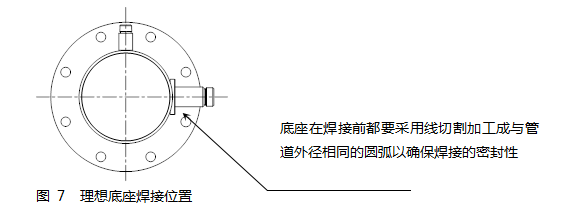
The base can be divided into standard and simplified types according to different installation methods. During installation, the base should be located at the top of the pipeline section direction and the axis of the base through-hole should be perpendicular to the pipeline axis.
Ideal welding position and welding process for the base (as shown in the figure below)


Refer to Appendix 1 Figure (Simplified Thermal Gas Mass Flowmeter)
Please confirm the actual inner diameter and wall thickness of the pipeline before installing a simplified thermal gas mass flowmeter.
Install the remaining parts of the thermal gas mass flow meter together into a dedicated ball valve, and calculate the depth to be inserted based on the actual pipe inner diameter and wall thickness. This step can insert a rough size and tighten the nut by hand.
Rotate the sensor connecting rod so that the marked arrow is in the same direction as the flow of the medium.
Based on the on-site measured data, convert the corresponding scale on the sensor connecting rod and tighten the nut.
If you are installing horizontally, the display screen of this instrument can be flexibly installed at 90 °, 180 °, and 270 ° to meet your actual on-site needs.
Refer to Appendix 2 Figure (Full tube thermal gas mass flow meter)
※Please confirm the connection method of the pipe section again before pre installation, and prepare items related to flange connection, such as gaskets and bolts.
※Production must be stopped before installation and relevant factory regulations must be strictly followed.
The full tube type instrument has correctly assembled the sensor on a dedicated pipe section when leaving the factory. Users only need to assemble the pipeline on site, so it is simpler to install compared to the on-site plug-in type. Firstly, select a suitable installation point on the pipeline, and then cut the pipeline according to the length of the necessary supporting pipe sections, install corresponding flanges and bolts. The determination of fluid flow rate should be consistent with the flow rate label marked on the full tube thermal gas mass flowmeter. And the display screen should be perpendicular to the horizontal plane, and the pipeline axis should be parallel to the horizontal plane, with an error of no more than ± 2.5 °. Finally, lock the instrument with bolts.
